Lab 3: Actuating the turtlebot in simulation
Contents
7. Lab 3: Actuating the turtlebot in simulation
Worksheet Contact: Xiao Wang (x.wang16@leeds.ac.uk)
Please aim to complete this worksheet during week 4. The labs scheduled in week 4 will offer support and guidance for this worksheet.
Note
Access lab3 files - Instructions As always, before you start running any commands or code for this worksheet, make sure you are in a Singularity environment.
Then execute the following commands:
In a terminal, go to
cd ~/ros2_ws/src.Run:
git clone git@github.com:COMP3631-2026/lab3 lab3Note the ” lab3” at the end of the the command:
git clone [...] lab3.
Run
cd $HOME/ros2_wsand thencolcon buildto build the new package.
7.1. Worksheet Objective
The objective of this worksheet is to help you understand how to control the robot and how to use it in a simulator. You will expand upon the concepts learned in lab 2 and implement the publishing-subscribing pattern to give commands to the robot.
7.2. Prerequisites
Before you start working on this worksheet, make sure to do the following one-time configuration:
Open a terminal window and navigate to your workspace’s source directory:
cd ~/ros2_ws/src.Git clone the following:
git clone git@github.com:COMP3631/turtlebot3_simulations.git(make sure you have an SSH key with GitHub as instructed in lab 1).Navigate to your workspace and rebuild:
cd ~/ros2_ws && colcon build.Remember to work in Code with the embedded terminals or run
source ~/.bashrcin the current terminal.
Warning
You can safely ignore the following warning message:
--- stderr: turtlebot3_gazebo
CMake Warning (dev) at /usr/share/cmake-3.22/Modules/FindPackageHandleStandardArgs.cmake:438 (message):
  The package name passed to `find_package_handle_standard_args` (PkgConfig)
  does not match the name of the calling package (gazebo).  This can lead to
  problems in calling code that expects `find_package` result variables
  (e.g., `_FOUND`) to follow a certain pattern.
Call Stack (most recent call first):
  /usr/share/cmake-3.22/Modules/FindPkgConfig.cmake:99 (find_package_handle_standard_args)
  /usr/lib/x86_64-linux-gnu/cmake/gazebo/gazebo-config.cmake:72 (include)
  CMakeLists.txt:23 (find_package)
This warning is for project developers.  Use -Wno-dev to suppress it.
If you get any errors, however, try deleting install and build directories
under ros2_ws/ and run colcon build again.
Warning
If you encounter this error while launching turtlebot3_space.launch.py:
[gzclient-2] gzclient: /usr/include/boost/smart_ptr/shared_ptr.hpp:728:
typename boost::detail::sp_member_access<T>::type boost::shared_ptr<T>::operator->() const [with T = gazebo::rendering::Camera;
typename boost::detail::sp_member_access<T>::type = gazebo::rendering::Camera*]: Assertion `px != 0' failed.

[ERROR] [gzclient-2]: process has died [pid 15429, exit code -6, cmd 'gzclient'].
you can run this in the terminal: . /usr/share/gazebo/setup.sh
then try to launch again.
7.3. Start Gazebo
Gazebo is a simulator, making it an ideal platform for programming a simulated turtlebot. Starting in simulation offers several advantages, including convenience and safety for experimentation. After successfully developing a functional demo in the simulated environment, we can confidently deploy the software onto a physical robot.
Let’s start a Gazebo instance. Open a new singularity terminal window and run:
Note
Gazebo may require a few minutes to launch the first time. Gazebo will initiate a download process and generate new files on your computer for the first time. Please wait until a new window displaying the virtual environment with the robot is launched.
ros2 launch turtlebot3_gazebo turtlebot3_space.launch.py
This will open the Gazebo simulator, allowing you to interact with the Turtlebot and various objects within a simulated environment. To adjust your view, use your mouse’s scroll wheel for zooming in and out. For rotation of your perspective within the world, press and hold your mouse’s middle button while moving the mouse. Additionally, you can experiment with the left and right mouse buttons for further exploration of the three-dimensional virtual environment and the robot.
At the top of your screen, you will see a menu, like the one below:

Gazebo menu
Currently, the leftmost pointer mode is selected. In this mode, your mouse movement adjusts your view within the virtual world. Now, please select the second mode from the left, which looks like a cross with arrows. In this mode, you can click and hold on an object within the virtual world, allowing you to drag and reposition it. This mode lets you move objects, including the robot, as if they were any other item in the world.
7.4. Turtlebot ROS nodes and topics
In the Gazebo environment, various ROS nodes run in the background, providing fundamental functionalities for the Turtlebot. These include the controller for the TurtleBot’s mobile base, drivers for its sensors, and more. If you wish to view a list of all running ROS nodes, open a new terminal and execute the following command:
ros2 node list
and inspect the result. Many of the nodes are named to explain their functionality, so try to guess what each one does. Similarly, to see all the ROS topics that are advertised, do this:
ros2 topic list
These topics include all the essential components necessary for the
operation of the Turtlebot. Are you able to locate the one
labelled cmd_vel? As its name implies, this topic is used for sending
velocity commands to control the mobile base of the robot. It will be an
important topic in our activities today.
7.5. Understanding the velocity topic
To see the publishers and subscribers to the topic, run:
ros2 topic info /cmd_vel
The subscriber of this topic controls the mobile base. To move the robot, we will write a new node that will publish to this topic.
The ros2 topic info command also shows us the type of the topic. It is
geometry_msgs/msg/Twist. If we want to publish to the topic, we need to use this
type. What is in a geometry_msgs/msg/Twist type? The command ros2 interface show is
useful for that:
ros2 interface show geometry_msgs/msg/Twist
The result shows us that Twist is actually a type that contains two other types
in it, specifically the Vector3 type. Each Vector3 type includes three float
values. Notice that one of the Vector3 types are named linear and the other
angular. It is becoming more clear now: This is a message type to specify
linear and angular velocities in three dimensions.
7.6. The firstwalk program: moving forward and backwards
You will find the file firstwalk.py in lab3 directory. This program
moves the robot back and forth in an infinite loop.
While Gazebo is running, run this script in a separate terminal window,
and see what happens:
ros2 run lab3 firstwalk
Now stop it by pressing: CTRL+C. Let’s study the code together as there are
multiple things going on to get this simple program working!
Please open the firstwalk.py file and read the following explanation. This
will help you understand how the program works.
7.6.1. Importing important modules
1from geometry_msgs.msg import Twist
2from rclpy.exceptions import ROSInterruptException
3import signal
Note that we import few new things:
Line 1: Since we need to publish to
cmd_velwhich expects aTwistmessage, we need to import that message type.Line 2-3: We need to respond to a ROS interrupt exception to ensure the robot stops moving. When a command is sent to the robot, if the program unexpectedly terminates (e.g., due to being killed), the robot may continue moving. Therefore, it is essential to catch and handle these exceptions to ensure the robot stops moving.
7.6.2. Creating the publisher
1self.publisher = self.create_publisher(Twist, '/cmd_vel', 10)
2self.rate = self.create_rate(10)  # 10 Hz
The above lines appear in __init__:
Line 1: we create a publisher to publish velocities to
/cmd_vel, note the new type,Twist.Line 2: we create a rate object at 10 Hz to help us send velocities at the specified frequency.
7.6.3. The walking forward and backward methods
1def walk_forward(self):
2    desired_velocity = Twist()
3    desired_velocity.linear.x = 0.2  # Forward with 0.2 m/s
4
5    for _ in range(30):
6        self.publisher.publish(desired_velocity)
7        self.rate.sleep()
Now the interesting part, the walk_forward and walk_backward methods which
moves the robot forward and backward:
Line 2: we create a
Twistobject. This object represents Twist messages, which define velocities. It is initialised with empty velocities, meaning both linear and angular velocities are set to zero.Line 3: we specify that the linear \(x\) velocity is
0.2, which is in meters per second (i.e., the robot will move at 20 cm per second). Note, as you would expect, these velocities are not instantaneously achieved and they are accelerated up to.Line 5: we create a for loop that executes 30 times.
Line 6-7: we publish the Twist message and then sleep using the rate object. The rate object maintains a constant loop rate of 10 Hz. With 30 iterations, the loop will execute and publish velocities to the robot for a total of 3 seconds.
The same idea applies for
move_backwardbut we use-0.2linear \(x\) velocity instead.
7.6.4. The stop method
1def stop(self):
2    desired_velocity = Twist()
3    self.publisher.publish(desired_velocity)
Nothing special happens here. The robot might continue moving even if we
stop publishing Twist messages. To guarantee the robot’s halt, we send a single
Twist message with zero velocities. Note that a new Twist object will initialise
with zero velocities, so we don’t have to explicitly set velocities to zero.
7.6.5. Main explained: infinite loops in ROS and how to handle interruptions
Please note that the main function has some additional complexity this time. We
will only explain new concepts introduced here. For previously covered topics,
please refer back to previous labs. In this program, we continuously move the
robot forward and backward within an ‘infinite’ loop. We need to implement a
robust mechanism for handling keyboard interruptions. The following sections
refer to code in the main function.
7.6.5.1. Main: Signal catching
1def signal_handler(sig, frame):
2    first_walker.stop()
3    rclpy.shutdown()
4
5# ...
6
7signal.signal(signal.SIGINT, signal_handler)
In the code snippet above, we define a function that gets invoked when the user
presses CTRL+C on UNIX-like systems, signalling an interrupt to the process.
This function ensures that the robot will stop moving after our code has been
terminated, by sending zero velocities and then explicitly triggering the
shutdown method of the ROS API.
7.6.5.2. Main: Running spin in a thread
1thread = threading.Thread(target=rclpy.spin, args=(first_walker,), daemon=True)
2thread.start()
The code above starts the rclpy.spin(first_walker) in a separate thread.
This allows ROS to start communications while enabling us to execute other
commands concurrently. By running it in a thread, we ensure that it runs
asynchronously, preventing it from blocking the main program flow.
7.6.5.3. Main: Infinite loops in ROS
1try:
2    while rclpy.ok():
3        first_walker.walk_forward()
4        first_walker.walk_backward()
5except ROSInterruptException:
6    pass
Finally, the code above shows the correct approach to running infinite
loops in ROS. We utilise rclpy.ok() to check if ROS is actively running
before executing our ROS commands, such as walk_forward and walk_backward.
7.7. Exercises
The turtlebot is capable of moving forward, backward, turning left and right. However, it cannot go sideways. In mobile robots, its type is called the differential drive robot. In robotic motion planning, this means there are non-holonomical constraints to its motion. This is basically a fancy way of saying it cannot go sideways. But it also means the robot needs to turn itself before going ahead in a specific direction. And if turning and moving forward/backward (relative to the robot’s body frame) happens at the same time, e.g. doing a donut without drifting, its velocity is tangent to the donut at any instance. Similar to a car, the robot is free to go anywhere on a 2D plane. But to park into the bay, you have to do a bit of manoeuvre.
In this excercise, you will be sending the velocity commands to the turtlebot to make it move around. It would be helpful if you can at least understand a bit of rigidbody motion, such as a twist. Hopefully, when you type the numbers in, the robot’s motion matches your intuition! So let me try to explain it here:
First of all, it is a vector \(\mathcal{V} = [\boldsymbol{\mathcal{v}} \;\; \boldsymbol{\omega}]^T = [v_x \;\; v_y \;\; v_z \;\; w_x \;\; w_y \;\; w_z]^T \in \mathbf{R}^6\), that lumps together angular and linear velocity. It describes the
instantaneous motion of a rigid body. It is needed to have a reference frame when talking about motion.
The Twist in this case is relative to (expressed in) the robots body frame \(\boldsymbol{\{b\}}\),
as illustrated:
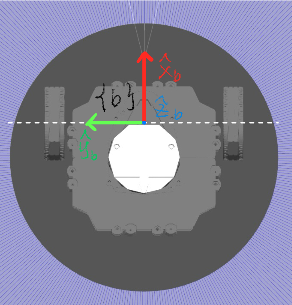
Illustration for turtlebot body frame, located at the mid point of the wheel axial.
If you are not familiar with mechanics, just remember the body frame is attached to the robot body and
goes with it. The choice of a reference frame is arbitrary in general, but the right choice simplifies
the problem dramatically. In this case, we choose the frame as illustrated. Not only does this conform
to the message type in turtlebot3_simulations package, but also to make the calculation simpler. This
is because the \(\hat{x}_b\) aligns with the direction of motion (or the velocity of the robot) at any
time instance. To give you some intuition, imagine the robot is moving forward, its velocity is just
pointing forward; if to be expressed in \(\{b\}\), it aligns with \(\hat{x}_b\). If the turtlebot is doing
a donut, at any instance, its velocity is tangent to the donut, then again aligns with \(\hat{x}_b\) if
to be expressed in this frame.
For the turtlebot, the configuration space is only 3d since it is just a planar system, i.e.
\(\mathcal{C} = [x \;\; y \;\; \theta]^T \in \mathbf{R}^3\) with respect to the world frame \(\{w\}\).
However, the dimension of the velocity you can command is only \(\mathbf{R}^2\) because of the
non-holonomic constraints (If you are math-hard, go check out Pfaffian constraints in motion planning).
Therefore, you can only command \([\dot{x} \;\; \dot{\theta}]^T = [v_x \;\; \omega_z]^T\) in the body frame
\(\{b\}\), which corresponds to moving along \(\hat{x}_b\) and rotating around \(\hat{z}_b\) axis. \(v_y = 0\)
is just not being able to go sideways. Without loosing generality, the Twist in ROS2 is 6D. When you
are sending the twist commands, you should only send to \(\omega_z\), \(v_x\). The other components are all
zeros by default. You can publish to the other components but makes no effects.
Now, to bridge your intuition to the physical concept of a twist, let’s separate linear and angular components first. Setting \(\omega_z\) to a +/- value will make it spin along \(\hat{z}\) in place clockwise/ counter-clockwise (right-hand rule); setting \(v_x\) to +/- value, it will move forward and backward. These are easy to understand. But what if I set \(v_x = 0.2\) and \(\omega_z = 0.2\) at the same time? I bet your mind tells you that it will trace a circle. Now I ask: based on these two numbers, do you know how big the circle is?
Before I show you the calculation. I would like you to bury this notion in mind: the axis of rotation can be moved around as long as it is parallel to \(\hat{z}_b\). When setting both angular and linear components, we are really asking for this: where should we put the axis of rotation in \(\{b\}\), and rotate around it at \(\omega_z = 0.2\), such that \(v_x = 0.2\) in \(\{b\}\)? To know the radius of the rotation, we only need a simple equation: \(\mathcal{v} = \omega \times r\), with \(\times\) being a cross-product. Because we are interested in the velocity of a point in \(\{b\}\) that just overlaps with the origin of this frame at any time instance! In our case, \(v = \omega \times \vec{PO}\), where \(\vec{PO}\) is directed from where the axis of rotation is in the \(x-y\) plane to the origin of \(\{b\}\). This is illustrated in the following figure:
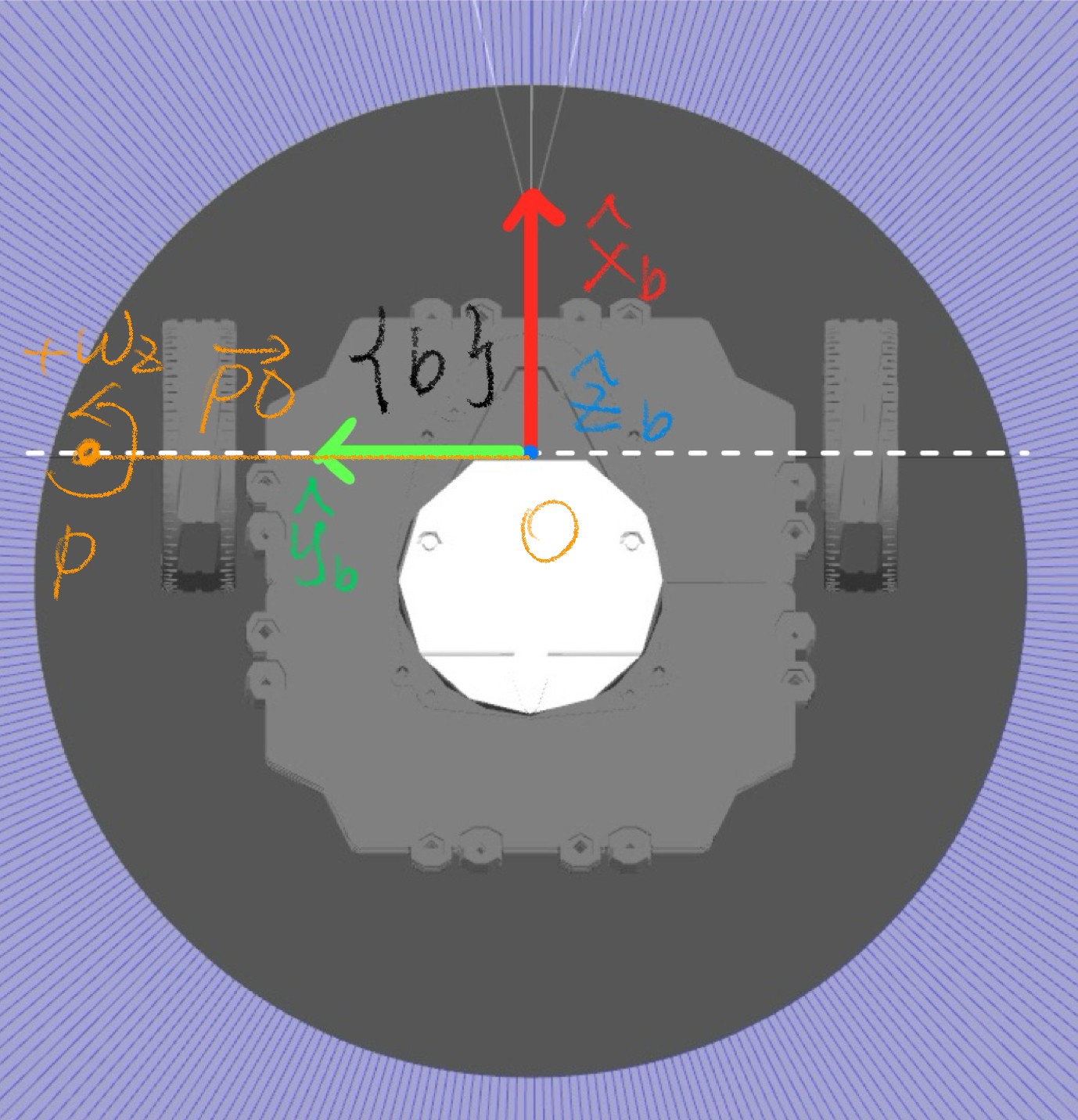
Illustration for a twist calculation.
The white dashed line is where the axis of rotation can be (Why is this? Diff drive can only go forward
i.e. \(\hat{x}_b\) with our choice of assigned body frame). The orange dot is the axis of rotation directed
out of the screen (same as \(\hat{z}_b\)). Then if you apply right-hand rule (imagine trying to grab the axis of
rotation with your right hand, and with your thumb pointing out of the screen), the direction of the curl of your
palm is the positive angular velocity (\(+\omega\)) by convention. Then imagine you have a disk with its centre
overlaps the orange axis of rotation and just as big to have its rim overlapping point \(O\). If it is spinning
at \(\omega_z\), at any instance, what is the velocity of a point on the rim that currently overlaps point \(O\)?
The answer is: \(v = \omega \times \vec{PO}\), which points along \(+/-\hat{x}_b\) depending on the sign of
your \(\omega_z\). Now we have all the elements to command a twist as you wish. Here is the math:
Let’s say the axis of rotation is located at \([0, y, 0]\), which is the orange dot expressed in \(\{b\}\).
Let’s express \(\vec{PO}\) in body frame \(\vec{PO} = [0 \;\; -y \;\; 0]^T\)
We know \(\omega = [0 \;\; 0 \;\; \omega_z]^T = [0 \;\; 0 \;\; 0.2]^T\)
We know \(v\) already: \(\mathcal{v} = [v_x \;\; v_y \;\; v_z]^T = [0.2 \;\; 0 \;\; 0]^T\)
Apply the expression: \(v = \omega \times \vec{PO}\), then you have \([0.2 \;\; 0 \;\; 0]^T = [0 \;\; 0 \;\; 0.2]^T \times [0 \;\; -y \;\; 0]^T\)
Expand the cross product on the right hand side, and evaluate to obtain the only unknow \(y = +1.0\) , which is the radius of the traced circle.
So in this example, with you commanding \(v_x = 0.2\) and \(\omega_z = 0.2\), the robot will trace a circle with a centre always located to the left (\(+\hat{y}_b\)) of the robot at a distance of 1.0m. If you keep \(v_x\) the same but increase \(\omega_z\), it will trace a smaller circle but faster. Now for a reflection, think again what is a twist? As we said, it describes the instantaneous motion of a rigid body. In this case, specifically the motion refers to whether the robot is moving straight or turning. If we have two cases, such that one robot moves at \(\mathcal{V} = [0.2 \;\; 0 \;\; 0 \;\; 0 \;\; 0 \;\; 0]^T\) and the other at \(\mathcal{V} = [0.2 \;\; 0 \;\; 0 \;\; 0 \;\; 0 \;\; 0.2]^T\). At any instance, the robot are moving forward in \(\hat{x}_b\) direction in the body frame at the same speed. But the latter tells you that it is turning while the former is just going straight ahead. In fact, any rigid body motion can be expressed as rotating about an axis located somewhere; if there is only linear velocity, the axis of rotation is just located at infinity! To be more general intuition: try imagine kicking a football with a body frame welded at its centre of mass, the ball (so does its body frame) moving forward in a curve (without considering the ball’s spinning); along its trajectory at any point in time, there is an associated axis of rotation located somewhere. This axis of rotation is changing with respect to time in the Catesian space, with which there is an associated twist to describe its instantaneous motion! Whereas in our case with turtlebot, the axis of rotation stays constant because we are commanding a constant twist. If our command is governed by a differential equation, then our robot will be rotating around a changing axis over time! Furthermore, if we are interested in a motion of a point located on the surface of the football in \(\{w\}\) frame, we need to take its spinning into account, i.e. \(v_p = v_{ball} + \omega_{ball} \times r\), where the twist of the ball in \(\{w\}\) is \(\mathcal{V}_{ball} = [v_{ball} \;\; \omega_{ball}]^T\). There is a recursive pattern to the compounded motion if you have a chain of frames to consider. Search for exponential coordinates of rigid body motion for a manipulator if you want to know more!
Finally, the hardware enforces limits on the turtlebots velocities: \(v_{x-max} = 0.22\;m/s\) and \(\omega_{z-max} = 2.84\;rad/s\). Now you can fiddle with how big of a circle and how fast you can trace!
Note
After creating the new scripts for each exercise below, remember to update the
lab3/setup.py file by adding a line for each new script. To ensure ROS
recognises your new Python files, execute colcon build within your workspace
after updating the setup.py.
Hint
For the two excercise, if you do not stop it after doing the circle or square, it will continue doing it
in the while loop in main(). If you want to do a complete cirle and stop, the limit in the for loop matters,
which together with the command frequency controls how long it will move at the Twist you set. This would also
be useful for making a square, e.g. controlling the angle and edge length of the square.
7.7.1. Exercise 1: Drive the robot in a circle
Create a script named exercise1.py within the ros2_ws/src/lab3/lab3
directory to continuously drive the robot in a circular path. Utilise a loop to
consistently publish a single Twist message, which combines both angular and
linear velocities to achieve a smooth and well-defined circular motion. Don’t
forget to update setup.py (see note box above).
You can test your solution after running colcon build with the following command:
ros2 run lab3 YOUR_TARGET_NAME
where YOUR_TARGET_NAME is the name you assigned to the script in setup.py.
7.7.2. Exercise 2: Trace a square
Create a script named exercise2.py within the
ros2_ws/src/lab3/lab3 directory to get the robot in tracing a square.
Keep in mind that the angular velocity is measured in radians per second, with
positive values indicating anti-clockwise movement. Consider this when
programming the turns to achieve a well-defined square shape.
Don’t forget to update setup.py (see note box above)
You can test your solution after running colcon build with the following command:
ros2 run lab3 YOUR_TARGET_NAME
where YOUR_TARGET_NAME is the name you assigned to the script in setup.py.
7.8. Remarks and Checklist
This worksheet covers various key aspects. Initially, you were introduced to
the Gazebo simulator. You explored the
cmd_vel topic for publishing a Twist to control the robot. You gained the
knowledge of some rigidbody motion, enabling you to accomplish both circular movements
and square tracing.
Please check, by the end of this worksheet, that …
You understand how to use the Gazebo simulator.
You can see a realistic world in Gazebo with the TurtleBot in it.
You understand how to move the robot.
You completed successfully the two exercises (move on a circle and move on a square).
7.9. Exercise Solutions
Please check this github repo for exercise solutions. This solution will be made available at the end of each corresonding week.
If you have any questions or problems, please kindly ask one of the Teaching Assistants of the module for help during the lab hours, or contact me.