Lab 4: Mapping and Navigation
Contents
8. Lab 4: Mapping and Navigation
Worksheet Contact: Xiao Wang (x.wang16@leeds.ac.uk)
Please aim to complete this worksheet during week 5. The labs scheduled in week 5 will offer support and guidance for this worksheet.
Note
Access lab4 files - Instructions As always, before you start running any commands or code for this worksheet, make sure you are in a Singularity environment.
Then execute the following commands:
In a terminal, go to
cd ~/ros2_ws/src.Run:
git clone git@github.com:COMP3631-2026/lab4 lab4Note the ” lab4” at the end of the the compand:
git clone [...] lab4.
Run
cd $HOME/ros2_wsand thencolcon buildto build the new package.
8.1. Worksheet Objective
Thus far, you have developed the skills necessary to work with ROS, publishing/subscribing to topics and drive the robot’s base in Gazebo. In this worksheet, you will learn how to create a map of a known environment and leverage it to navigate the robot within that space collision-free.
8.2. Introduction
The TurtleBot is equipped with ROS software, facilitating collision-path planning within a known environment. The process is two-fold:
Mapping: A map of the environment is needed for a motion planner:
You tele-operate the robot (using the keyboard or a joystick) in the environment. While you do this, the robot uses its sensor to create a map.
You save this map to a file.
After this point, as long as the environment does not change (i.e. the obstacles do not move significantly) the robot can use this map for navigating autonomously in the environment. If the environment changes significantly, you will need to re-map.
Navigation: The robot navigates autonomously using the existing map.
You can give a goal pose to the robot, and it can plan a collision-free path and then follow the path.
To know where it is in the environment, the robot uses its sensor for localisation too.
The objective of this lab is to familiarise you with the mapping
and navigation software on the TurtleBot.
Many of the functionality you will use in this lab comes from the
turtlebot3_cartographer and turtlebot3_navigation2 packages. You can find
a wiki page here.
8.2.1. Launch Gazebo with a new world file
Start the Turtlebot simulation with the house world. To do this, execute in a terminal window:
ros2 launch turtlebot3_gazebo turtlebot3_house.launch.py
The first time you launch the new world, Gazebo may take a few minutes to load. Please be patient. A new world should launch that looks like the one below.
Typically, the robot starts outside the house; therefore, you will need to move it inside. Please follow the steps outlined in the following image:
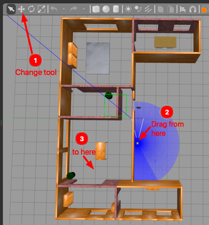
You need to move the robot in the house first so we can map the house.
8.2.2. Mapping
Let’s start with mapping the new environment. In a new terminal run:
ros2 launch turtlebot3_cartographer cartographer.launch.py use_sim_time:=True
The launch file above initiates not only the mapping software but also Rviz, a visualisation tool that displays the map as it is being built. In Rviz, the areas of the map that have already been built are indicated in red. At this point, you should see a similar screen with the one below:
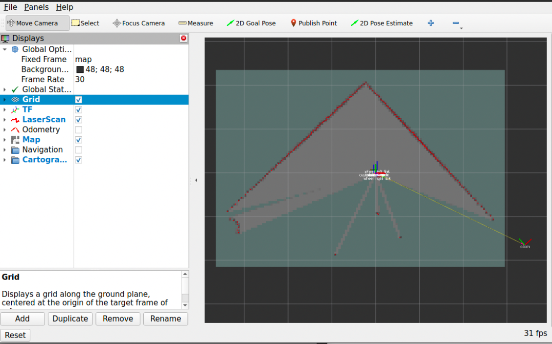
Screenshot of Rviz when initially starts. The red part is the map being built so far.
8.2.3. Tele-operating the TurtleBot
Note
You can utilise the identical program for tele-operating both the simulated and the real TurtleBot. This is feasible because both the simulated and actual TurtleBots receive the same messages to the same topics. Therefore, the tele-operation software is agnostic to whether it is interacting with the real or the simulated robot; this seamless integration is made possible by the abstraction capabilities of ROS.
To map the environment you need to move the robot around. The turtlebot3_teleop
package is used to tele-operate the TurtleBot. We will use the keyboard for
teleoperation. In a new terminal window run:
ros2 run turtlebot3_teleop teleop_keyboard
Pay attention to the instructions displayed on the screen regarding the movement of the robot. It’s important not to hold the keys down continuously. In brief:
Use
wto increase andxto decrease linear velocity. Remember not to keep these keys pressed.Use
ato increase anddto decrease angular velocity (spin). Again, do not hold these keys down.Use
sor the space bar to bring the robot to stop.
8.2.4. Exercise 1: Build your own map of the environment
To create a map of the environment, you’ll need to move the robot around using the method described above.
You can track this process in Rviz. This is a process that can take 10+ minutes for you to complete. You need to make sure your robot sees all edges, corners, and obstacles in the environment. You should make a few rounds in the environment so that the robot collects as much information as possible. As this is a big environment, you may focus on mapping only two rooms instead of the full house. Of course, you are welcome to map the entire house.
Here are some tips and tricks for better mapping:
Avoid colliding with any obstacles or walls while driving the robot. Such collisions can alter the environment’s layout and potentially render your map inaccurate.
Move the robot at a slow pace. Rapid movement tends to yield less reliable results.
Direct the robot towards interesting features within the room. By ‘interesting,’ we refer to features that are not symmetric or too common, like unique obstacles. For instance, a flat wall mirrored on the opposite end of the room won’t provide much valuable information. Seek out areas with obstacles and non-symmetric characteristics.
When near such interesting features, pause and slowly rotate the robot around that spot 2-3 times.
If you notice any inaccuracies in a specific region, revisit that area with the robot, move more slowly, and rotate around the region to enhance the map’s accuracy.
Please note that the map will never be perfect.
8.2.5. How good should my map be?
A good map doesn’t have to be perfect. Take the example map provided below as a reference. The key aspect of a good map is to accurately represent obstacles and clearly delineate openings between rooms and doors. Any black marks on the map are interpreted as obstacles, and the robot is programmed not to cross these areas. These could represent walls, bins, or any other form of obstruction.
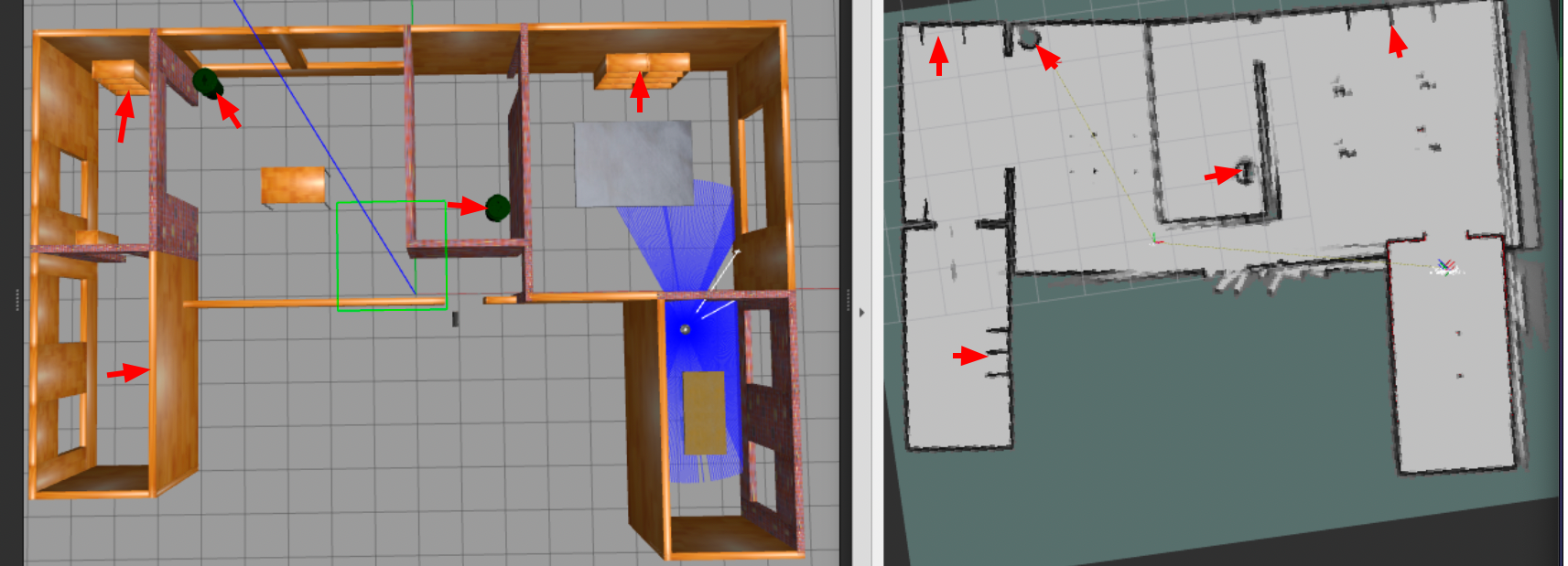
Here is an example of a good map
8.2.6. Saving your map to a file
Once you’re satisfied with the map in Rviz, the next step is to save this map to a file. For this purpose, you should execute the following command in a separate terminal window:
ros2 run nav2_map_server map_saver_cli -f $HOME/ros2_ws/src/lab4/maps/mymap
Upon successfully saving the map, you should find two files located in the
$HOME/ros2_ws/src/lab4/maps directory: mymap.pgm and mymap.yaml. The
.pgm file is the actual map, which you can view as an image. The .yaml file
contains meta-data about your map.
Congratulations on creating a map of the environment! This map is now ready for use in autonomous navigation, and you won’t need to repeat this process for the current environment unless there are significant changes.
At this point, you can safely shut down (using ctrl-c) both the mapping and
the teleoperation processes.
If your map doesn’t turn out as expected, you can always use the provided
example map files: examplemap.yaml and examplemap.pgm. However, it’s highly
recommended to practice and learn how to create a map yourself.
8.3. Navigation
Now that you have successfully constructed a map, you can try to command the robot to go somewhere using the Rviz GUI. Remember that, when you use the autonomous navigation stack, to kill the tele-operation node as it can interfere with the navigation node.
To initiate navigation, execute the following command in a new terminal window, ensuring that you replace the placeholder path to a map file with the actual path to your map file:
ros2 launch turtlebot3_navigation2 navigation2.launch.py use_sim_time:=True map:=$HOME/ros2_ws/src/lab4/maps/mymap.yaml
This should start the navigation stack along with Rviz. Once you have Rviz opened, you should see the map loaded into it.
8.3.1. Letting the robot know (roughly) its initial pose
At this stage, it’s necessary to localise the robot within the map to give it an approximate starting point. Observe the robot’s location in Gazebo, paying attention to the direction is pointing to. Then, in Rviz, select the ‘2D Pose Estimate’ button. Next, click and hold on the map at the robot’s location and use the mouse to orient the robot in the correct direction. This step is important as it helps the robot localise itself in the map. You don’t have to be perfect, but roughly right. Refer to the image below for a visual guide on how to perform this action:
Use the “2D Pose Estimate” tool. Click on the point in the map where the robot is located. A green arrow will appear. Keep the mouse clicked and move the mouse to set the direction the robot is facing. Once you have aligned the arrow with the robot’s orientation, release the mouse.
8.3.2. Sending navigation goals to the robot through Rviz
You are now ready to send navigation goals to the TurtleBot. To do this, use the ‘2D Nav Goal’ button in Rviz. After clicking this button, select a point on the map where you want the robot to go, and specify the direction you want it to face upon arrival. You do this by clicking and holding at the chosen point, then dragging the mouse to set the desired direction. Once you release the mouse, the robot will begin navigating towards the set goal, while avoiding obstacles along its path. For a visual demonstration of how to set a navigation goal, refer to the image below:
Set navigation goals to robot using the “Nav2Goal” button. Again, click and hold to define the orientation.
Congratulations! Your robot is autonomously navigating now.
8.3.4. How to find the coordinate in the map?
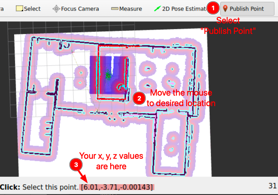
To determine the \(x\), \(y\) coordinates of a specific point you wish to navigate to, use the “Publish Point” feature in RViz. First, select the “Publish Point” option from the top menu in RViz. Then, hover your mouse over the desired location on the map within RViz. As you move your cursor across the map, RViz will display the coordinates (\(x\), \(y\), \(z\)) of the point under your mouse in the lower-left corner of the RViz window. This tool is particularly useful for pinpointing precise locations on the map for navigation purposes. An example of this process can be seen in the image provided below:
8.3.5. Exercise 2: Now your turn, find a new x, y coordinate to move the robot to
Using this method, you can determine the \(x\), \(y\) coordinate you want to specify in
the script.
Go ahead and find a new coordinate to command the robot to move to.
Modify the Python script to inject your new coordinate. Don’t forget to run
colcon build under ~/ros2_ws/ after your changes.
Execute the script and your robot should plan and move to the goal you specify:
ros2 run lab4 go_to_pose
8.3.6. Exercise 3: Think how you would design your motion planer?
A few points to consider:
With the map (black being the obstacles and white being the free space) and the reference frame to which it associates, we have our configuration space of the robot \(\mathcal{C}\).
Each pixel is assigned with a coordinate relative to the frame. The map is essentially a discretization of a continuous space. Do we need such a high dimension space to search for the coordinate (or linear pose) to tackle a navigation task?
Can we do some dimension reduction? Such as discretizing the free space by squares, then only search through patches; heuristics, and sampling based methods, potential field, etc.
8.4. Remarks and Checklist
As you conclude this worksheet, you have now developed all the necessary skills to work on the project in a simulated environment. Next week you will have the opportunity to apply these skills to a real robot! Yay!
Please check, by the end of this worksheet, that …
You understand the difference between mapping and navigation.
You know how to generate a map using the ROS tools.
You know how to set initial estimate of the robot’s pose in the map.
You know how to use the map to send navigation goals to the robot through RViz.
You know how to use the map to send navigation goals to the robot through Python code.
You completed successfully the exercise of generating a map and modifying the Python script to move to a new goal.
You pushed your files to GitHub.
8.5. Exercise Solutions
Please check this github repo for exercise solutions. This solution will be made available at the end of each corresonding week.
If you have any questions or problems, please kindly ask one of the Teaching Assistants of the module for help during the lab hours, or contact me.